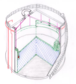
The design basis of the standard Linerbag product includes a fixated, non-mobile, part being positioned in the bottom half of the steel tank and a mobile top half moving with the liquid level. The fixated bottom half of the Linerbag is suspended at the circumference at half way height of the tank from a hoisting ring with tension ropes (cables) or belts. The top half is thus hanging, from the half way suspension height, entirely inside the bottom half with the roof resting on the Linerbag floor, when there is no liquid inside and is positioned in a reversed manner on top of the bottom half when the tank is 100% full. The mobile Linerbag top half comprises a fixed shaped circular roof part with floating capabilities and a cylinder shaped side wall, which moves along the inside of the Linerbag lower half at filling rates below 50% and along the inner tank wall at filing rates of over 50%. The fully enclosed, “submerged”, type of Linerbag uses a “heavy ring” to pull down the Linerbag cylinder shaped side wall material not being used to create the necessary volume for the stored liquid, below the liquid surface level such that the heavy ring always is positioned at the lowest possible position. This results in all Linerbag side wall material to be under a certain (low) tension level and thereby allows for the predictability of the stresses and strain in every part of the Linerbag material and for bending of material in accordance with the radius of the heavy ring while folding of the material is avoided.
The schematic on the left hand side of this text shows an open cut fixed roof tank. The tank half filled with liquid (marked: blue) positioned inside a Linerbag (marked green). The Linerbag is suspended from half the height of the tank using a hoisting ring and tension belts. The left side of the tank demonstrates the submerged, heavy ring version

