Slosh mitigation of LNG; New Products
Erik Jeroen Eenkhoorn
Hengelo (O), The Netherlands
ABSTRACT
Slosh mitigation has been researched for several years now and proven products thereto were developed, especially such for liquid slosh mitigation in horizontal cylinder-shaped mobile tanks like those tanks being part of mobile tanks and tank containers. The design of slosh mitigation products, as researched, comprises an inflatable element which is placed inside the mobile tank. The scientific and fundamental functional principles have been subject to prior ISOPE papers and presentations, refer Eenkhoorn 2014,2017, 2018).
Key functional requirements for slosh mitigating products with a design based on the use of an inflatable element include:
- The membrane material of which the inflatable element is fabricated requires to be of a high Young’s modulus, i.e. in the order of 109 N/m2,
- The contact surface of the membrane of the inflated component and the liquid inside the mobile holder requires to be tensioned.
This is not different for slosh mitigating products for use in rectangular mobile tanks like in tank ships. There are however main differences between the “2-dimensional” (“length” and “diameter”) fundamentals of horizontal cylinder-shaped mobile tanks commonly with a diameter of some 2.5 meters maximum and “3-dimensional” (length, width and height) fundamentals of rectangular mobile tanks especially such with a length and width (much) larger than 2.5 meters. One of the key differences is caused by the reduction in the ratio of the membrane wall thickness over the length or width of the mobile tank.
The basis for design of slosh mitigating products for large rectangular tanks using inflatable elements is therefore not based on such element transferring forces between mobile tank and liquid via the contact surfaces of the inflated element with both tank or liquid. The slosh mitigation functional requirements may be arrived at by using an inflated “parachute”, mattress type of slosh mitigating element covering the top liquid surface. This inflated “parachute”, mattress type of element by its radii of curvature enforces a surface tension on the top layer of liquid creating a stable mass of liquid as well as eliminating the possibilities of turbulent interactions of liquid and air or vapours over the liquid or of wave creation. The mass of liquid affected by the surface tension provides for a large momentum of inertia resulting in relative slow and limited movements or rotation under dynamic conditions of the mobile tank. Creating such radii of curvature in inflated “parachute”, mattress type of slosh mitigating element can now also be achieved by the recently patented design of elements with a relatively small working height.
KEY WORDS
Sloshing, Slosh mitigation, Stability, Slosh mitigating products, Inflatable component, rectangular mobile tanks.
INTRODUCTION
The application of inflatable component products in mobile tanks have been researched and developed by the author over the last decade. (Eenkhoorn, 2017a) This research also concluded that no prior research including inflatable components in mobile tanks had been done before. While liquid dynamics and slosh mitigation remain to be a very scientific and theoretical subject, developed slosh elimination products or liquid load securing products are not. Slosh eliminating devices are very practical and technically not complex. Slosh mitigating products, refer Ibrahim, RA 2005, are limited to various designs of baffle plates. Such baffle plates continuously dampen the liquid but do not secure liquid cargoes.
Inflatable component products aim firstly at avoiding sloshing of liquid cargoes which only partially fill the tank they are transported in. Avoiding sloshing results in a better stability of the mobile tank, hence in less keeling-over or jack-knifing risks and in shorter break distances, especially at higher initial mobile tank speeds at the commencement of breaking. Inflatable components ensure transfer of all necessary forces between means of transportation and liquid during braking i.e. deceleration and during acceleration. They thereby assure that all kinetic energy of the liquid when breaking commences is dissipated by the brakes. Without inflatable components and in case of baffles applications, the liquid remains sloshing after the means of transportation, i.e. the mobile tank, has stopped. The liquid then must lose its kinetic energy through a damping process of the liquid. The kinetic energy gets converted into heat in this process. Elimination of sloshing of liquids not only improves the stability but thus also reduces the energy consumption by the liquid during transportation and reduces the rate of vaporization (or the boil-off-rate in case of LNG).
As inflatable components in their basic design generally contain all the air which otherwise would be “free” inside the liquid filled tank, there is no longer any free air present inside the mobile tank. Consequently, there is no contact between air and liquid. As a consequence, when there is no air nor any other void space inside the tank when an inflatable component product is used, the liquid cannot evaporate. There are thus no longer vapours which may cause emission issues.
Initial research into slosh mitigation in mobile tanks other than of a horizontal cylinder-shaped design and the subsequent development of slosh mitigating products for such tanks has been approached as follows.
- The fundamental principles as research for horizontal cylinder-shaped mobile tanks were analyzed especially on aspects typically and possibly only being applicable for horizontal cylinder-shaped mobile tanks.
- Subsequently these principles were re-examined on the consequences and impact of the change of the shape of the mobile tank to a rectangular shape.
- Next, concept designs for inflatable component-based slosh mitigating products for rectangular mobile tanks were created.
- And conclusively, concepts for new slosh mitigating products were developed for rectangular type of mobile tanks including LNG containment systems.
THE USE OF INFLATABLE COMPONENTS FOR SLOSH MITIGATION IN PARTIALLY LIQUID FILLED MOBILE TANKS
The design of a functional inflatable component product is a process which consists of several steps to come to a reliable, well performing, long lasting slosh mitigation product. (Eenkhoorn, 2014). The inflatable component design as researched and developed for horizontal cylinder-shaped mobile tank covered both the inflatable component features in slosh mitigating performance terms as well as the interfaces between the inflatable component, the tank it was to be positioned in, and the means of transportation.
The two prime functional slosh mitigating requirements of an inflatable component are:
- the shape retention of the component in its inflated condition, and
- the ability to transfer loads
Shape retention.
As tanks are commonly steel, metal made hence rigid and non-deformable and as liquids are hardly compressible, both the tank and the liquid fill volumes remain constant during transportation. The volume of the inflatable component hence has to remain constant as well during transportation. Displacement of the liquid relatively to the tank requires shape changing of the inflatable component. Shape retention of an inflatable component can be arrived at in two manners:
- Full inflation of the component to an internal pressure which is higher than the highest pressure in the liquid occurring at any stage during transportation of such liquid. This principle is used in the so called “fixed volume” inflatable components.
- Tensioning of the inflatable component material at the liquid contact surface and subjection of all other parts of the inflated component material to friction forces higher than the forces which can be generated by the liquid during transportation thereof. This principle is used in the so called “variable volume” inflatable components.
Load transfer.
Slosh mitigation as concluded by mentioned research, resorts under “load securing”. Any hardware cargo being transported is secured prior transportation. No corrective actions are undertaken during transportation, nor shall be required. The driver of the means of transportation is to focus on the traffic surrounding the means of transportation and the behaviour of the means of transportation as under his or her control and responsibility. Cargo (load) and means of transportation shall have identical speeds and accelerations at each and every moment during transportation. This requires all necessary forces to be transferred unconditionally and instantaneously between loads and means of transportation. Load securing is not about energy destruction, baffle plates causing the liquid to dissipate energy are hence not a means of load securing even though sloshing may be reduced as a result thereof.
Further design challenges for horizontal cylinder-shaped mobile tanks included amongst others:
- the absence of any provision in the tank required to support or maintain the position of the inflatable component. The design allows hereto for two separate air chambers being used and being operating at slightly different pressures of each other.
- One air chamber, the air channels, are to ensure the proper shape of the component. The main chamber is to allow for the variation in the specified volume range.
- the inflatable component system is preferred to include functions ensuring the liquid overfill protection. Common stand-alone overfill protection devices works under atmospheric conditions in free air present inside the tank. This condition changes when inflatable components are used.
- Dangerous goods, liquids applications result in additional mandatory specifications like ÄTEX” and compliance with dedicated laws (especially the “ADR”), with laws on emissions and with legislation on the construction of means of transportation.
The further research and development of inflatable components for mobile tanks, including LNG membrane tanks, other than horizontal cylinder-shaped versions thereof may be based on the research and development of inflatable components for horizontal cylinder-shaped mobile tanks. (Eenkhoorn, 2017)
THE USE OF FIXED VOLUME INFLATED COMPONENTS FOR SLOSH MITIGATION.
The inflatable fixed volume cylinder-shaped component
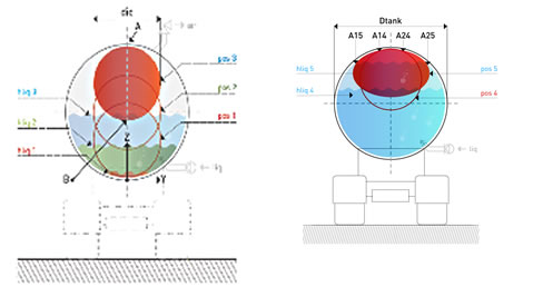
Figure 1. Showing a cross section of a horizontal cylinder-shaped tank in which a fixed volume, inflated component is present (left-hand part of figure) which rises from position “1” via position “2” to position “3”.
At this last position, the first (line) contact “A” with the inner wall of the tank commences. The liquid height “hliq” is measured from the lowest point of the tank (z=0). The compression of the inflatable component when the liquid level is further raised as shown (right-hand part of figure) to position “4” with inner wall contact surface radially stretching between “A14” and “A24”. Ultimately position “5” is reached in which the volume of the inflatable component and the volume of the liquid are equal to the volume of the tank. The contact surface now stretches from “A15” to “A25”. The inflated component has obtained an oval shape in the final liquid fill process.
The fixed volume inflatable component of a cylinder-shape obtains shape retention by tensioning of its membrane material caused by the internal inflation pressure of the component. The internal inflation pressure is higher than the (peak-)pressures occurring in the liquid during transportation, thus also ensuring shape retention of the component in extreme circumstances. The inflated component becoming submerged during the liquid filling of the tank is thereby increasingly subjected to upward forces. These upward forces and resulting friction forces as well as the dimensioning of the component in relation to the tank dimensions ensure:
- A stable, constant position of the component in the tank, and;
- The transfer of all transportation related forces between the component and the tank and vice versa.
Cylinder shaped inflatable components in rectangular tanks
A rectangular mobile liquid holder may also be provided with a fixed volume inflatable component, comprising cylinder-shaped elements, to reduce the effective liquid working volume of the tank while avoiding sloshing of the liquid filling the remainder of the tank. The concept design of such application must ensure the inflated component to remain in the required position in the (top of the) tank during the liquid fill and emptying processes. A fixed volume inflatable component, comprising cylinder-shaped elements may be dimensioned such that there are (larger) contact surfaces between the inflated component and the inner tank wall(s). The internal pressure of the inflated component may be designed to ensure substantial friction forces between the component and the inner tank wall. A component with a grid of multiple cylinder-shaped inflated elements may ensure sufficient friction forces to be available to keep the component in its designed for and required position even in conditions whereby there is no liquid inside the mobile tank. Mechanical fixation of the component at positions remote of any inner tank wall may also be considered. As the cylinder-shaped elements of the inflated components have either a line contact or a small contact surface of narrow width with the inner roof of the tank, the exposure of the roof to upward forces exercised by the component will remain to be taken care of and engineered for..
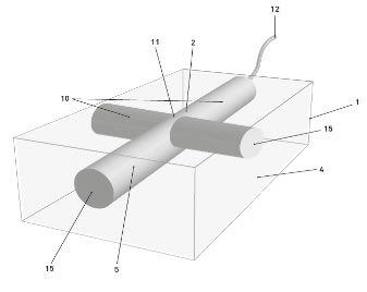
Figure 2. Showing a rectangular tank 1 being part of a means of transportation, for example a ship, in which a fixed volume inflated element 2 comprising legs 10 and one cross 11, all filled with inflation gas 5, is present. The volume of the fixed volume inflated element 2 limits and reduces the volume of the tank 1 being available for the liquid 4. The element 2 with inflation and deflation provision 12 may remain in a fixed position in tank 1 aided by friction forces at the contact surfaces 15 between the element 2 and the inner wall of the tank 1.
The theoretical basis of creating liquid stability using a cylinder-shaped inflatable component in a mobile tank is based on the theoretical basis of the liquid filling process in which the following four stages can be identified:
(1) The “free rise” stage.
The “free rise” stage of the liquid filling process starts with the component being fully inflated to its design pressure “PIC”, positioned over the liquid filling the tank until to the situation arises whereby the liquid touches the component and whereby the component touches the top of the inner tank wall, at (line contact) “A”, see fig 2.
(2) The “last air expulsion” stage
The “last air expulsion” stage of the liquid filling process starts with the inflatable component remaining in increasing contact with the top of the inner tank wall while the liquid ultimately fills up all space in tank with expulsion of the last free air.
(3) The “liquid only compression” stage
The “liquid only compression” stage commences with the holder being 100% filled with the inflatable component combined with liquid, of which the top is at atmospheric pressure, and continues until the pressure in the liquid (at position “B”, see figure 2) is equal to the pressure in the inflatable component.
(4) The “liquid and inflatable component compression” stage
The “liquid and inflatable component compression” stage commences when the value of the pressure in the liquid is equal to the pressure in the inflatable component at which the safeguarding device (relief valve) of the liquid holder opens and expels quantities of liquid equal to the ones being filled into the tank.
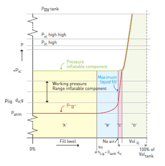
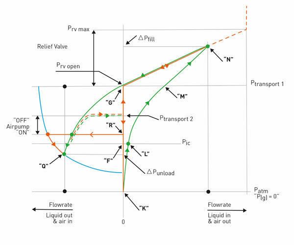
Figure 3. Development of the pressures in a fixed volume inflated component and in the liquid in relation to the liquid fill level of the liquid holder. Also shown are “stages 1 till 4” as detailed above. Identified are the recommended “maximum liquid fill level” and the operationally usable “working pressure range” of the inflatable component.
THE USE OF VARIABLE VOLUME INFLATED COMPONENT FOR SLOSH MITIGATION.
The inflatable, variable volume, component for horizontal cylinder-shaped mobile tanks.
The physical principles of an inflatable variable volume component, as used in subject studied case and specified hereinafter, are very different from those for a fixed volume component. Refer the “Anti-slosh Inflatable Component Performance in relation to Rigidity and Load Transfer” ISOPE 2017 Paper (Eenkhoorn, 2017b).
The variable volume inflatable component obtains shape retention by tensioning of its membrane material caused by:
- Firstly, the liquid building up an overpressure when entering the tank. This pressure increase is required to force the air out of the inflated component and to start moving the component material upward.
- Secondly, the liquid re-positions to its lowest possible center of gravity as soon as the tank fill process is stopped and the liquid over-pressure is no longer present.
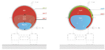
Figure 4. Showing a cross section of a horizontal cylinder-shaped tank in which an also horizontal cylinder-shaped inflated component, made of a rubber or thermoplastic material with a high Young’s modulus, is present. The underside of the inflatable component rises from position “1”, the “no liquid” position via positions “2” to “5”, the “100% liquid filled” position.
The behaviour of an inflatable component with a variable volume working range during transportation of a liquid cargo is determined by the liquid fill process of the tank. A brief fill process description commences with the situation of a mobile tank (in a stationary position) without containing any liquid, inherently being 100% filled by the inflated component.
The inflatable component commences to deflate upon the tank being filled with liquid. The (lower) part of the inflatable component, becoming in contact with the liquid, rises thereby from its lowest position to its top position whereby all the to-be-loaded liquid is inside the tank and whereby there is no more air inside the inflatable component. Refer pos. “1” till pos. “5”, figure 4.
The contact between the outer-surface of the inflatable component and the inner-tank wall reduces from the full circumferential contact to half the circumference at the point where the tank is 100% liquid (and deflated component) filled. The material becoming “spare” accumulates in “flaps” against the inner tank wall.
There is no “free” air inside the tank at any time. The internal pressure of the inflatable component “PIC” remaining constant in the liquid loading process of the tank and is equal to the set pressure of the relief valve “PRV” through which the air used to inflate the inflatable component is expelled to outside the tank.
The pressure difference “ΔPfill” between the air and the liquid sides of the component membrane causes the membrane to curve and to be subject of stress. This stress will cause the spare membrane material to commence bending in the flap (line “1”, figure 5) and to be pulled away from the inner tank wall during the liquid fill process. This is the start of a process called “the formation of flaps”. The higher the liquid level rises, the more membrane material becomes “spare” and the larger and the more submerged these flaps therefor become.
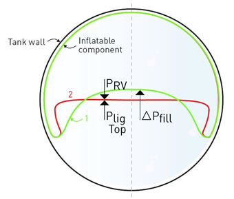
Figure 5. Component liquid contact surface change from liquid fill (“1”) to post liquid fill (“2”)
When, at any point, before or when the tank reaches its maximum (i.e. 100% -/- volume of the deflated component) fill, the liquid filling process is stopped, the over-pressure in the liquid forcing air out of the inflatable component disappears. The liquid surface will reshape from slightly curved to flat as there is no longer a pressure difference between the air and the liquid side of the component membrane. The bending radius of the flap decreases (line “2” in figure 5) and the flap folds rather than bends and gets forced by the hydrostatic pressure against the inner tank wall.
In constant liquid volume situations, i.e. during transportation, the liquid hydrostatic pressure results in sufficiently high (friction) forces at the contact surfaces between the component membrane material of the flaps and at the contact surfaces between the inner tank wall and the flap membrane. Such level of friction forces does not occur in the liquid fill situation as there are no contact surfaces between the component membrane material of the flaps. Such contact is avoided provided the opening pressure of the relief valve is higher than the highest occurring hydrostatic pressure in the liquid occurring at the most submerged point of the flap. Refer also Figure 6.
The inflatable, variable volume, component for rectangular mobile tanks.
The explorative investigation into applying an air-filled bag in a rectangular mobile tank established firstly that the liquid / free air contact surface remains constant, both in size and dimensions, for any fill level, i.e. in the direction of the z-axis, the only variable over the 0 to 100% fill range of the tank. Note: This also applies to vertical cylinder-shaped tanks.
Secondly, it was established that mobile rectangular tanks requiring slosh mitigation are primarily part of bunker ships and sea-going oil tankers. These mobile rectangular tanks are (much) larger in volume than the common, road and rail used, horizontal cylinder-shaped means of transportation. Generally, the ratio’s length over height and width over height of rectangular tanks are more than in case of horizontal cylinder-shaped mobile tanks. Furthermore, larger rectangular tanks are seldom (or not) built as “pressure vessels”, unlike horizontal cylinder-shaped tanks.
Furthermore, and thirdly, the liquid partially filling these mobile rectangular tanks is subject to sloshing caused by sea motions, i.e. waves, rather than by high levels of acceleration or by high centrifugal forces related to going through sharp curves by mobile tanks on roads.
The rectangular, variable volume, inflatable component concept.
Concept designs may be based on applying a rectangular, variable volume, inflatable component. Such component, identically to the horizontal cylinder-shaped version, by design, will have to contain all otherwise “free” air.
Excess (“spare”) component material at any liquid fill level more than 0% of the holder, must be accumulated in “flaps”, in case slosh mitigation fundamentals identical to cylinder-shaped components are envisaged to be applicable.
In rectangular tanks with a width and length much larger than common diameters of horizontal cylinder-shaped tanks (~2.5 meters), there will be too much (horizontal) liquid contact surface material. Too much liquid contact surface material results either no curvature, hence no stability, or a curvature of a very high radius, requiring too high tensions to create stability. Variable volume slosh mitigating concept designs based on only a basic rectangular inflatable component of identical dimensions and shape as the large mobile tank, it is to serve and perform in, therefore cannot be considered. Concept designs based on applying multiple chambers, air channels etc. ensuring slosh mitigating functionality in case of flap and ensuring shape retention of the liquid contact surface became to be a research challenge.
A rectangular, variable volume, inflatable component design concept meeting the above requirements is provided in Figure 7.
This invention, furthermore, provides for a new design for an inflatable element, refer 2 in Figure 7, enabling the securing of any liquid pay-load or volume, refer 4 in Figure 7, when inflated, variable within a 0 to 100% range of the volume of the rectangular mobile tank, refer 1 in Figure 7, in which the element is applied. This new design comprises an element, refer 2C in Figure 7, of the same rectangular shape, sizes and dimensions as the mobile tank it is applied in and comprises in its most basic design at least one separately inflatable compartment, refer 2A in Figure 7, of at least one cross, refer 11, of two horizontal cylinder-shapes legs, refer 10, when inflated. In addition, the design may include furthermore, separately inflatable horizontal cylinder-shaped channels, refer 2b in Figure 7, especially in such surface of the element which is in direct contact with the liquid top surface. The separate inflation of the cross of two horizontal cylinder-shapes legs is to ensure the development of the appropriate radius of curvature and stress and strain levels of the wall material of the inflatable element at its contact surface with the liquid during a liquid volume change of the mobile rectangular tank, i.e. during liquid loading or off-loading. The addition of separately inflatable horizontal cylinder-shaped channels, refer 2B in Figure 7, may be used to reduce, by deflation, or increase, by inflation with air or inflation gas refer 5 in Figure 7, the stress and strain of such surface material of the inflated element which is in direct contact with the liquid top surface. Furthermore, the inflatable element may be provided with inflatable channels to ensure the rectangular shape and correct positioning of all element material even when the mobile tank does not contain any liquid. The variable volume element comprises the main inflation chamber, refer 2C in Figure 7, with dedicated inflation provision, refer 13 in Figure 7, the radius of curvature ensuring inflation cross, refer 2A in Figure 7, with dedicated inflation provision, refer 12, and the stress manipulation inflatable channels, refer 2B in Figure 7, with dedicated inflation provision, refer 14.
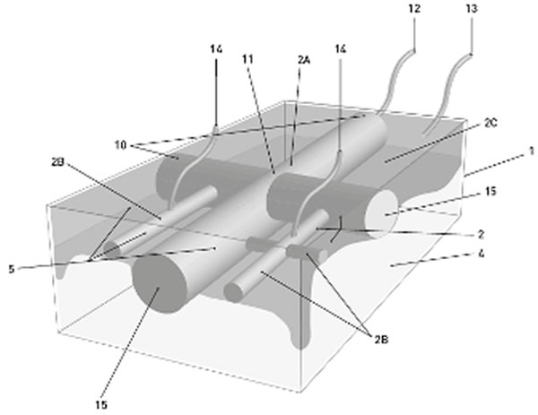
Figure 7. provides and shows a concept design of a rectangular variable volume inflatable component based on applying multiple chambers, air channels etc. ensuring slosh mitigating functionality of flap, as far as these are formed during liquid filling of the tank, and ensuring shape retention of the liquid contact surface, as shown in a rectangular tank.
When the mobile rectangular tank, refer Figure 7, is in a situation without containing any liquid, the inflated element chambers 2C fill the entire tank space and volume, while channels, refer 2A and 2B Figure 8 (top) are deflated. In case the rectangular mobile tank is in a condition of being partially liquid filled, refer Figure 8 (middle), at any stage in the liquid fill process of the mobile tank, the inflatable element chambers, refer 2C in Figure 8, deflate and do so continuously during the liquid fill process of the mobile tank. The internal pressure of the inflatable element chambers and its inflation gas is to remain higher than the highest hydrostatic pressure encountered outside the chambers at the lowest position of the flaps. Simultaneously channels, refer 2A and 2B in Figure 8 (middle), are inflated over the first 50% liquid fill interval and deflated over the remaining 50-100% liquid fill interval. In case the liquid filling of the tank is stopped, the mobile tank remains fully or partially liquid filled at a constant volume of liquid, in which condition the redundant material of inflatable element chambers, refer 2C in Figure 8 (below), provides for the deflated flaps, while channels, 2A and 2B remain possibly partially inflated subject to the specific liquid fill rate of mobile tank. In case the tank is 100% liquid filled, refer Figure 8 (below), the inflatable element chambers 2A and 2B are completely deflated.
Inflatable channels may be in a cross shape or any other shape, like rectangular channels with interconnections between the channels, to ensure liquid cargo securing over the full liquid top surface. The cross-sectional representations, as in Figure 8 apply for both the direction of transportation as for the perpendicular direction.
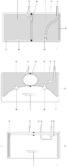
Figure 8A (top). shows a cross section of a rectangular tank 1, as in figure 7., and a variable volume inflatable element 2 with inflatable chambers 2C of which the curvature of the liquid contact surface is manipulated by inflatable channels 2A and of which the tensioning of the material is manipulated by inflatable channels 2B. The rectangular tank 1 is show in a situation without containing any liquid, whereby the inflated element chambers 2C fill the entire tank 1 space and volume, while channels 2A and channels 2B are deflated. Inflation gas 5 is transferable with inflatable element chambers 2C via connection 13, with inflatable channels 2A via connection 12 and with inflatable channels 2B via connection 14.
Figure 8B (middle). shows the rectangular tank 1, as in figure 7A. but in a condition that tank 1 is partially liquid 4 filled at some stage in the liquid 4 fill process of tank 1. The inflatable element chambers 2C deflate continuously during this process, while channels 2A and 2B are inflated over the first 50% liquid fill interval and deflated over the remaining 50-100% liquid fill interval.
Figure 8C (below). shows the rectangular tank 1, as in figure 7A and figure 7B. but in a condition that tank 1 is partially liquid 4 filled and the liquid 4 filling has stopped, in which condition the redundant material of inflatable element chambers 2C provide for the deflated flaps, while channels 2A and 2B remain partially inflated subject to the specific liquid fill rate of tank 1. In case tank 1 is 100% liquid filled, the inflatable element chambers 2C and channels 2A and 2B are completely deflated.
This concept design results in only limited upward forces on the inner roof of the tank exercised by the component, as a consequence of little liquid submersion. High spot loads on the inner tank wall are also avoided as there are no supports nor suspensions of the slosh mitigation product. Finally, there is no risk nor requirement of the inflatable component or parts of its material having to move over inner tank walls There are hence no associated high friction forces, risks of tear and wear and unknown foldability phenomena.
The “Mattress” concept
Variable volume slosh mitigating concepts do not only have to comprise “full volume” rectangular inflatable component designs.
A fixed volume mattress concept allowing for free air or vapours inside the liquid holder is another alternative. Details of such, refer Eenkhoorn (2018).
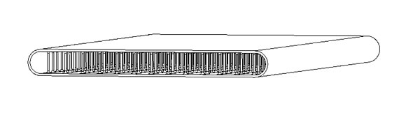
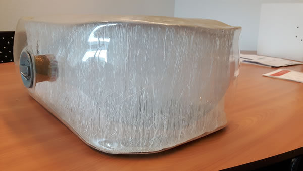
Figure 9. A “3D”, multiple string connected two sheet version.
The results of further research in the design concept of the prior (refer Eenkhoorn (2018) identified alternatives of the “Reduced liquid surface covering mattress” concept will be detailed hereinafter. This mattress design concept is based on the absence of any load transfer and of any interfaces of the mattress with the liquid holder or its walls, floor and roof.
The “counterweight” mattress version
A first version of this design concept comprised a normally flat (3D) inflatable mattress component which stabilises by its curvature by using a “heavy weight” submerged in the lower stable liquid part with spring and damping components between these two components. (As shown in Figure 10). The liquid surface covering area of the mattress is to be designed slightly smaller than the dimensions of the liquid top surface. The mattress will thus have no or little contact with the inner walls of the liquid holder. The liquid dynamic related forces being imposed on the mattress will be transferred to the submerged contra-weight by springs and dampers. Initial testing using a model, see Figure 11, showed promising slosh mitigating results.
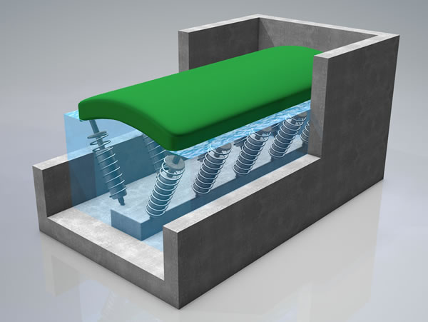
Figure 10. A 3-dimensional view of a fixed volume mattress being applied in a rectangular mobile tank, with load transfer to a submerged heavy weight via springs and dampers.
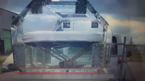
Picture 11. Experimental testing of a 3D material made inflatable mattress connected via springs and dampers to a heavy weight submerged in the stable liquid below the liquid top surface.
Reduced liquid surface covering mattresses do not require fixed connections to the inner wall, floor, or ceiling of the liquid holder; thereby avoiding high stress points in the holder, possible liquid holder re-certification obligations, etc. This is considered to be an advantage.
Reduced liquid surface covering mattresses are especially suitable for situations in which some “semi-static” movement of the liquid is desired. Such may be the case for tall tanker ships for which the desired loading requires a liquid displacement, from bow to stern, to obtain a specified maximum angle with the horizontal.
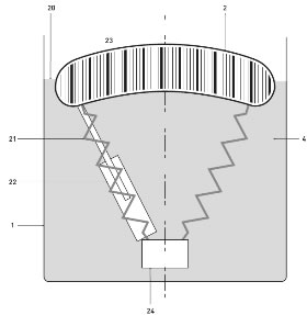 Figure 12. Schematic overview of a reduced liquid surface covering mattress” concept.
he scientific fundamentals of this concept comprise, refer Figure 12:
- The floating capabilities “Fup” of the inflatable component (number “1”in figure 12) have to be sufficient to ensure the inflatable component remaining at the liquid/vapour interphase of the LNG.
The inflation gas to be used to be less in specific gravity than the specific gravity of the liquid LNG. The submersion of the inflatable component thus to result in required upward forces. The inflation gas may be natural gas possibly at a (slightly) higher temperature than the boil-off temperature (-162 C). The use of natural gas as inflation gas will have the advantage of the permeability of the material of the inflatable component to be less critical. Other gases like Nitrogen when used as an inflation gas may affect the calorific values of the LNG in case of permeation through the component material. The concept design of the entire slosh mitigating contraption results in the edges of the inflated component to be pulled into submersion furthest. This results in a concave shape of the inflatable component as shown in figure 10 and thereby contributes to the slosh mitigation performance. - The non-covered liquid surface areas to be relatively small. “Rims” of less than one-meter width are envisaged to ensure both very little sloshing of the rim free surface liquid to occur and the inflatable component not to impact with the containment wall. The mass inertia of the entire inflatable component and contra-weight (number “2”in figure 12) being sufficiently high to ensure only very little vertical speed development of the slosh mitigating contraption, if any. Equally the contraption shall only exercise very little rotation due to the high level of mass inertia. The physical dimensions of the slosh mitigation contraption will ensure such.
- The spring and dampener provisions (numbers “3” and “4” respectively in figure 12) shall be designed and constructed in a flexible manner to allow for the entire slosh mitigating contraption to rest, likely in a “deflated” condition on the bottom of the containment system when such is not LNG filled. Accede developed “green textile” may well be used as a material for connecting the inflatable component with the contra-weight in a design manner providing for adequate elasticity and damping.
- The contra-weight shall be designed and constructed such that it can and will not harm, damage the containment system even in cases where it should move within the stable liquid phase in the lower part of the containment system. One concept may include a liquid nitrogen filled, “green textile” made blather. A liquid filled textile blather meets the “no damage on impact” requirement. Nitrogen can be used as a liquid as the specific gravity of liquefied nitrogen is more than of LNG, which is a key requirement for the contra-weight. In case Nitrogen is used there may be an interesting option to cool the liquid LNG (from within the containment system). The nitrogen may be circulated to cooling provisions outside the containment system to ensure the Nitrogen to remain at its boil-off temperature of -196 C while absorbing heat from the LNG in the contra-weight. The heat taken from the LNG should reduce the boil-off quantities of the LNG.
The “inflatable strap” mattress version
The inflatable mattress with the counter weight concept has considerable disadvantages like the built-in height and the required presence of a rather large volume counterweight. A more practical design concept version, refer Figure 13, is provided.
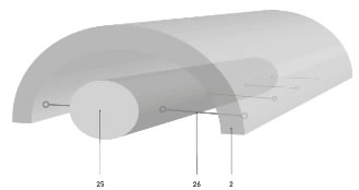
Figure 13. shows a mattress type of inflatable element (“2”) of a more practical design version for creating a curvature in the mattress, as the height of the element plus components is relatively small. The circumference of the mattress is connected by straps (“26”) to at least one inflatable channel (“2”05, as shown. Inflation of the channel(s) will cause the radius of curvature of element 2 to become more.
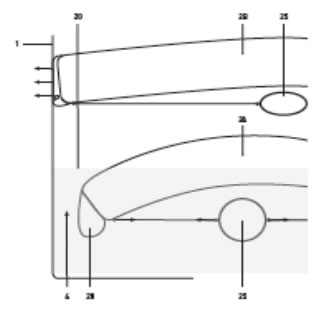
Figure 14. shows a detail of the mattress type of inflatable element 2, as in figure 13, in two conditions; firstly (2A) in a smaller radius of curvature with channel 25 fully inflated and secondly (2B) in a larger radius of curvature with channel 25 not fully inflated or even deflated. In the condition of the element 2 with a smaller radius of curvature, the mattress has no contact with the inner wall of the mobile liquid holder.
This is the preferred condition during liquid loading and off-loading. In the condition of the mattress 2 with a larger radius of curvature, the mattress has contact with the inner wall of the mobile liquid holder. This is the preferred condition during liquid transportation, in which a separately inflatable channel provision 28 may be used for the transfer of forces via friction between the inflatable mattress element and the inner wall of the mobile liquid holder.
The circumference of the inflated element, refer Figure 13, is provided with tension straps. These tension straps comprise strap sections interconnecting inflatable channels or crosses comprising multiple legs. Inflation of the inflatable channels, or inflatable crosses, by dedicated inflation gas provision results in the inflated element being forced into a radius of curvature. Deflation of the inflatable channels, or inflatable crosses, refer Figure 14, reduces the tension in the straps and thereby reduces the forces applied on the circumference of the inflatable mattress type of element, which will thereby resort to a flatter shape and horizontal condition. A separately inflatable chamber, refer 28 in Figure 14, may be applied to increase the friction forces between the inflated element and the inner wall of the mobile holder or to reduce the vaporisation of the liquid.
ENFORCED SURFACE TENSION BASED SLOSH MITIGATION
Although the basic rectangular shaped inflatable component, without any internal provisions, was discarded before, there may be opportunities for this principle. The attractiveness of pursuit of this design concept is its simplicity.

Figure 15. Example of a water droplet demonstration the surface tension principle
The slosh mitigating fundamentals could be based on applied surface tension physics.as are applicable for water droplets on surfaces, see figure 15.
The design concept shall be based on the following hypotheses:
- The surface tension value “γ”, determined by the choice of membrane material for the inflatable component and the liquid shall be as high as practically possible.
- The material of the inflatable component, especially such material possibly being in contact with the liquid at a certain liquid fill range of the tank, shall be “dimpled”. Such dimples preferably shall be shaped conforming to the liquid surface tension-based shape. Refer Figure 16. The contact surface of the inflatable component membrane may thereby be non-permeable as in Figure 16 or permeable, allowing for vapours to be present in the 3D material of the inflatable. component as in Figure 17.
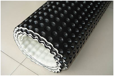
Figure 16. A “dimpled” contact surface of the inflatable component membrane with a non-permeable contact surface.
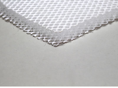
Figure 17. A “dimpled” contact surface of the inflatable component membrane with a permeable contact surface, allowing for vapours to be present in the 3D material of the inflatable component.
The physical fundamentals of surface tension being applied are:
The “Young-Laplace” equation:
Δp = γ ( 1/R1 + 1/R2 ) (1)
Where Δp is the Laplace pressure, the pressure difference across the fluid interface, γ is the surface tension (or wall tension) and R1 and R2 are the principal radii of curvature.
And the surface tension force “Fst “equation:
Fst = γL (2)
Where “L” is the length of the liquid surface.
Maximizing the surface tension within the membrane of the inflatable component is considered to be beneficial in terms of “shape retention” of the membrane at the liquid contact surface. Such shape retention, as mentioned in the introduction being essential to achieve slosh mitigation. The liquid trapped in its preferred droplet shape inside the dimples of the component membrane create “stiffness” or resistance against deformation. Furthermore, the “dimple trapped” liquid adds to the mass and the momentum of inertia of the membrane at the liquid contact level, making this membrane slower to respond to liquid dynamic processes.
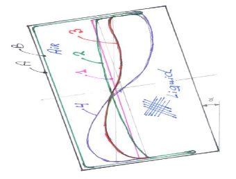
Figure 18. Effects of surface tension enforced membrane deformation in slosh mitigating rectangular inflatable components
Condition 1: Liquid surface in case α = 0°, without inflatable component. Condition 2: Liquid surface in case α = 0°, with an inflatable component. Condition 3: Liquid surface in case α > 0°, with an inflatable component of a high surface tension enforced membrane at the liquid contact surface. And condition 4: Liquid surface in case α > 0°, with an inflatable component of a low surface tension enforced membrane at the liquid contact surface.
CONCLUSION
Slosh mitigation of liquids in partially liquid filled rectangular mobile tanks is feasible. Research including small and scale testing in horizontal cylinder-shaped mobile tanks have proven so. Refer Eenkhoorn, EJ 2017a. Furthermore, slosh mitigation in such rectangular applications should be further researched and products to mitigate sloshing should be developed thereto. Preparatory work done so far and conceptual designs are encouraging and should provide the justification for undertaking further slosh mitigation research and product development for rectangular mobile tanks.
Numerical or experimental studies are envisaged to be part of suggested further research. Such research may be organized identically to the research method applied for slosh mitigation of liquids in horizontal cylinder-shaped tanks as established, refer Eenkhoorn, EJ 2017a. Identically results may be achieved with a virtual liquid fixation whereby only less than 0.1% of the liquid volume displaces semi-statically within a mobile tank which is subject to external dynamic influences.Materials have already been researched and developed specifically for LNG applications. Such materials, called “Green textiles”, are LNG compatible, even over a large temperature range of well below LNG boiling conditions (at -162 C) to near 100 C. These materials have been certified by, an included in the LNG material database of GTT.
REFERENCES
Eenkhoorn, EJ (2018), “Slosh mitigation applications in LNG containment systems”, Proc Int. Offshore and Polar Eng. Conf., Sapporo, Japan, ISOPE-2018. 2018-TPC-0368
Eenkhoorn, EJ (2017a), “Products to mitigate liquid sloshing”, Thesis 22 November 2017, ISBN 978-94-6233-808-1
Ibrahim, R.A., Liquid Sloshing Dynamics, Theory and Applications, Wayne State University, 2005, ISBN-13 978-0-521-83885-6.